Product Overview
Front Panel
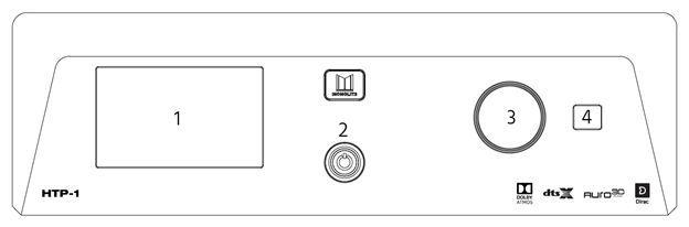
- LCD Display: This 5" touchscreen displays the volume level, selected input, upmix selection, and various other system statuses. See Front Panel Display below for details.
- Power Button: If the Master Power Switch on the rear panel is in the ON position, the front panel Power Button turns the unit on or puts it into standby. A blue LED illuminates the power button while the unit is powering on or powering off. The LED is extinguished when the unit reaches a stable state.
- Volume Knob: Rotate the Volume Knob counterclockwise to decrease the volume level or clockwise to increase the volume level.
- IR Receiver: The IR Receiver accepts infrared signals from the included IR Remote Control.
Front Panel Display
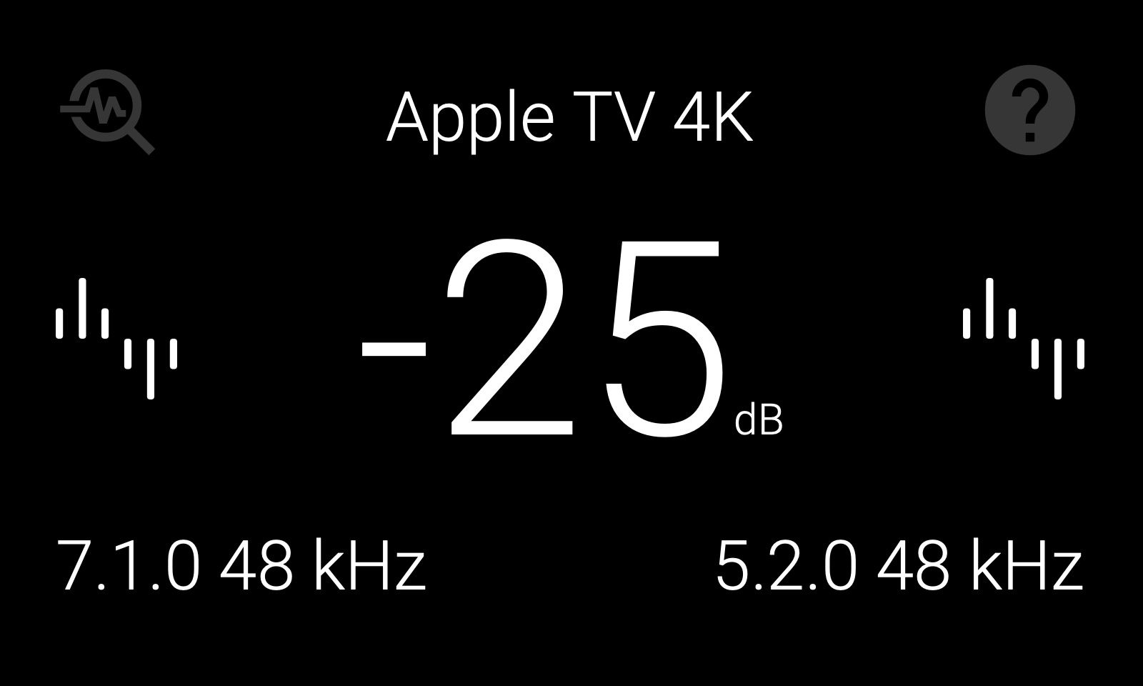
The touchscreen shows the current input, program format, volume, upmix selection, and other system status information, and doubles as a set of touch controls:
- Help icon (top right): Tap to open the Help screen, which shows network information and lets you reset the network connections. The icon turns red when no network connection is available.
- Peak monitoring icon (top left): Tap to start or stop Peak Monitor. While active, the display shows the highest peak level and its channel. See Peak Monitor for details.
- Input source display (top center): Tap to show video input details. This area also shows if the signal generator is on. Tap twice to view detailed playback and processing information.
- Master volume level (center): Tap to mute your HTP-1. Tap again to unmute. When muted, the display changes from white to red. The displayed value is the current master volume. 0 dB represents the configured Reference Output Voltage; negative values indicate attenuation below that level.
- Input format (middle left): Tap to show more details.
- Output format (middle right): Tap to show more details.
- Audio input details (bottom left): Tap to show more information about the audio input. Tap twice to view detailed playback and processing information.
- Audio output details (bottom right): Tap to show more information about the audio output. Tap twice to view detailed playback and processing information.
The front panel also provides the network information needed for first-time setup and access to the web interface. See Basic Setup for details.
The remote's color buttons provide shortcuts to several front-panel functions. See Remote Color Button Functions for details.
Rear Panel
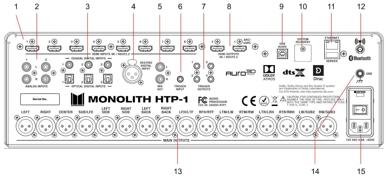
- HDMI INPUTS: Eight HDMI® inputs for connecting HDMI source devices. Each input supports 4K resolution and the HDMI 2.0b and HDCP™ 2.3 standards.
- ANALOG INPUTS: Two pairs of RCA analog stereo jacks for connecting an analog stereo audio source.
- COAXIAL/OPTICAL DIGITAL INPUTS: Three digital coaxial and three digital optical S/PDIF audio inputs for connecting digital audio sources. All six inputs are active and can be independently selected.
- AES/EBU DIGITAL INPUT: Three-pin XLR jack for connecting an audio device that outputs an AES/EBU (aka AES3) digital audio signal.
- MIX OUT: One pair of RCA analog stereo jacks for connecting a stereo amplifier or powered speakers. The main signal is mixed down to a stereo signal. Mix Out has its own volume and power-on volume, independent of the main outputs, set from the Home page and the Volume Setup page. Mix Out can also carry the Seat Shaker signal instead, in normal or differential mode.
- TRIGGER INPUT: A 3.5mm trigger input turns the HTP-1 on when a 12V signal is applied. The HTP-1 will go into standby mode when the trigger signal is removed. Note that the Master Power Switch on the rear panel must be in the ON position for the trigger signal to turn the HTP-1 on.
- TRIGGER OUTPUTS: Four 3.5mm jacks send a 12V trigger signal when the HTP-1 is powered on. These triggers are typically used to power on the power amplifiers.
- HDMI OUTPUTS: Two HDMI® outputs for connecting HDMI displays. The "HDMI 1" output supports the Audio Return Channel (ARC)/Extended Audio Return Channel (eARC) HDMI features, which receive audio signals from the connected display. This is necessary if you are going to stream video from an app on your TV or if you are receiving over-the-air television broadcasts using an HD antenna. The System Status page reports eARC connection status if you need to troubleshoot this link.
- USB AUDIO: A USB Type-B jack for streaming audio from a connected computer.
- SYSTEM RECOVERY: Mini SD card slot used by the factory for production purposes only. A factory restore procedure is available using this.
- ETHERNET/SERVICE: An RJ45 jack for making a wired connection to an existing Ethernet network. The USB port is for performing service at the factory.
- ANTENNA: An SMA connector for attaching the included Bluetooth®/Wi-Fi® Antenna.
- MAIN OUTPUTS: Sixteen balanced XLR jacks for connecting external power amplifiers. The channel labels silkscreened on the back panel are supplemented by the Speaker Map on the Speakers page of the web interface, which shows the current mapping for your speaker configuration.
- GND: Screw terminal for making a ground connection to the chassis.
- POWER SECTION: The POWER SECTION contains the Master Power Switch, the IEC Power Connector for attaching the included AC Power Cord, and a Fuse Holder. Always disconnect the power cord from the power source before replacing the fuse, and replace the fuse with the same type.
Tip
To assure a completely clean reboot, allow the HTP-1 to be powered down for 15 seconds before powering on again via the master power switch.
Remote Control
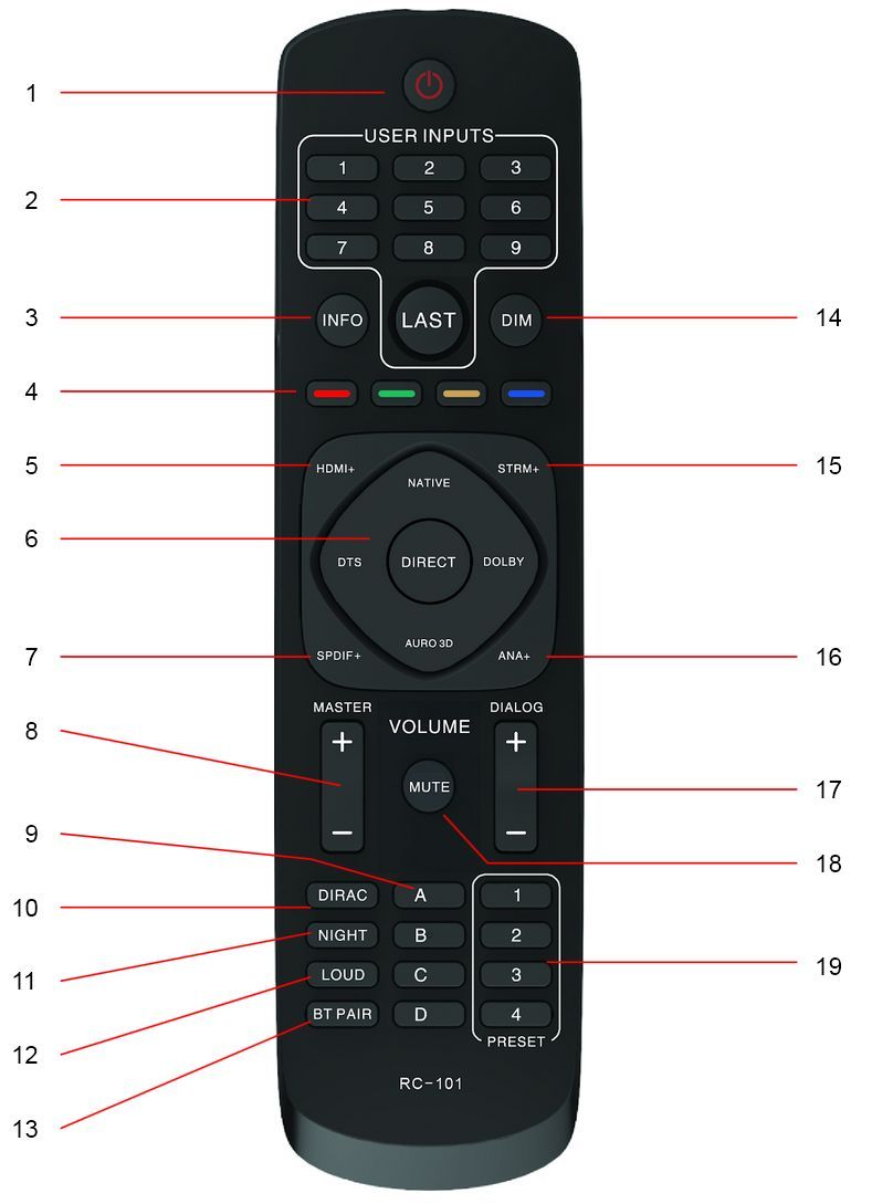
- POWER: Press the POWER button to turn the unit on or to put it into standby mode.
- USER INPUTS: Press the number buttons to select individual inputs. The numbers map to the visible inputs, from left to right, on the web interface Home page. Press the LAST button to select the last input used.
- INFO: Press the INFO button once for playback details and twice for audio processing status.
- COLORS: The Red, Green, and Yellow remote buttons control the front panel: Red displays the debug screen, Green displays audio processing status, and Yellow reloads the front panel. The Blue button resets the HDMI subsystem.
- HDMI+: Press the HDMI+ button to cycle forward through the eight HDMI® inputs as well as the TV input. When using this button the interface will display the HDMI input that will be selected after a short timeout period expires (about 3 seconds). This allows the user to rotate through the input options without actually changing the input (which can slow things down). This delayed input change only applies to this button, not any of the other + buttons.
- SURROUND MODES: Press the buttons to select the NATIVE, DTS®, DIRECT, DOLBY®, or AURO-3D® surround modes.
- SPDIF+: Press the SPDIF+ button to cycle forward through the digital audio inputs. The cycle order is COAXIAL 1, COAXIAL 2, COAXIAL 3, OPTICAL 1, OPTICAL 2, OPTICAL 3, and AES/EBU.
- MASTER: Press the + button to increase the MASTER volume level or press the - button to decrease the MASTER volume level.
- LETTERS: The A, B, C, and D buttons run whatever is assigned to those slots on the Macros page.
- DIRAC: Press the DIRAC button to cycle Dirac Live between on, bypass, and off.
- NIGHT: Pressing the NIGHT button rotates between off, auto, and on. Night mode is designed for low volume movie viewing. See more details under Audio Features.
- LOUD: Press the LOUD button to enable or disable Loudness mode, which boosts low and high frequencies for low volume music listening. This is described in more detail under Audio Features.
- BT PAIR: Press the BT PAIR button to initiate Bluetooth® pairing.
- DIM: Press the DIM button to cycle through several brightness levels for the front panel LCD display. When the dim level is zero, the screen will briefly brighten to show changes in volume.
- STRM+: Press the STRM+ button to cycle through the USB, Roon®, and Bluetooth® streaming inputs.
- ANALOG+: Press the ANALOG+ button to toggle between the two analog audio inputs.
- DIALOG: Press the + button to increase the DIALOG volume level or press the - button to decrease the DIALOG volume level.
- MUTE: Press the MUTE button to turn audio muting of all speakers on or off.
- NUMBERS: The preset 1, 2, 3, and 4 buttons run whatever is assigned to those slots on the Macros page.
Web Interface
The web interface is where you configure the HTP-1 and where day-to-day control happens from a phone, tablet, or computer. Reach it by typing http:// followed by the HTP-1's IP address into a browser's address bar — for example, http://192.168.1.101/. The front panel display shows the current IP address (tap the Help icon in the top right). Some browsers default to https://, which will not work; type http:// explicitly. Pages within the interface use hash-style addresses, such as http://<your-htp1-ip>/#/settings/speakers — bookmark the plain http://<your-htp1-ip>/ address rather than a settings page.
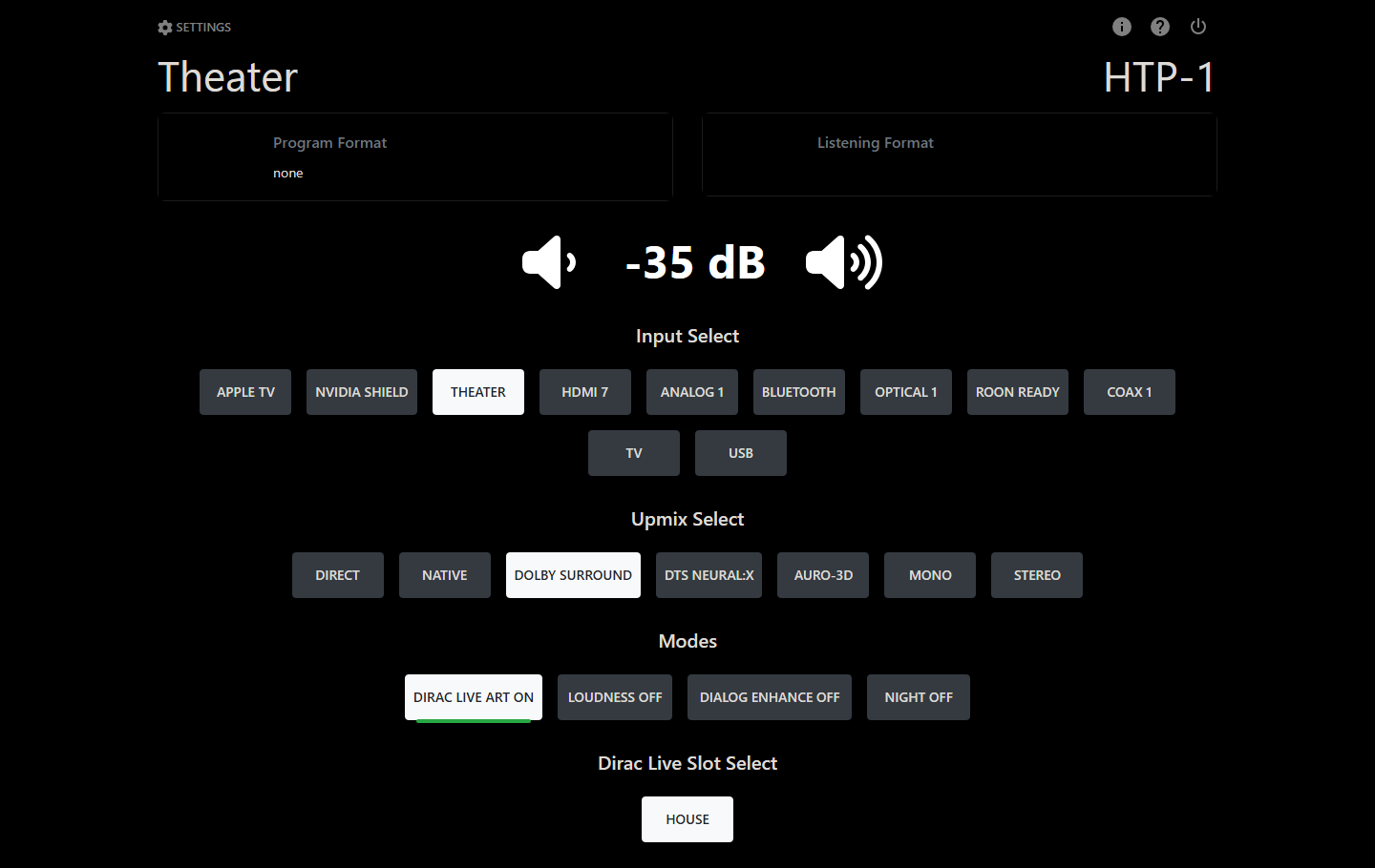
Home Page
The Home page is what you land on, and what most day-to-day control happens from:
- Your unit name is the page title, with the HTP-1 wordmark in the top-right corner.
- Program Format and Listening Format status cards report the incoming and actual decoded formats. A Video status card can also appear here, if enabled on Personalize.
- The Volume readout sits in the center, with tap targets on either side to step it up or down. If Mix Out is enabled, a second Mix Out Volume control appears below it.
- Input Select and Upmix Select button rows choose the active input and upmix mode. Which inputs and upmixes appear, and in what order, is set on the Inputs and Upmix pages.
- A row of Modes buttons toggles Dirac Live (a three-state on / bypass / off control), Loudness, Dialog Enhance, and Night (off / auto / on).
- If you have Dirac Live calibrations saved, a Dirac Live Slot Select row lets you switch between them directly from Home.
- Rows of macro buttons can also appear here, if you have set any up.
Which of these rows appear, and in what order, is controlled from the Personalize page. You may also see transient banners across the top of the screen — for example when the signal generator is left on, a macro is recording, or a Dirac Live calibration is in progress — reminding you that something is active elsewhere in the system.
Settings
Click the gear icon (labeled Settings) in the top-left corner of the Home page to open the settings area. It replaces the Home page with a sidebar down the left side and the selected settings page on the right. The sidebar lists Home at the top, then twenty pages in three groups, then Power Off at the bottom:
| Group | Pages |
|---|---|
| Speakers & audio | Speakers, Calibration, Channel Levels, Signal Generator, PEQ, Seat Shaker, Bass EQ, Tone Control, Loudness, Upmix |
| Setup | Inputs, Network, Macros, Personalize, Volume Setup, Peak Monitor, Device Settings, Configs |
| Status & help | System Status, Help |
Once you are inside settings, a small line of text at the top of the screen — <volume> dB · <input> · <upmix> — shows current status and links back to Home. A row of shortcut icons also sits in the top-right corner; which pages appear there is chosen on the Personalize page, so you can jump straight to the pages you use most.
System Status, Help and Power
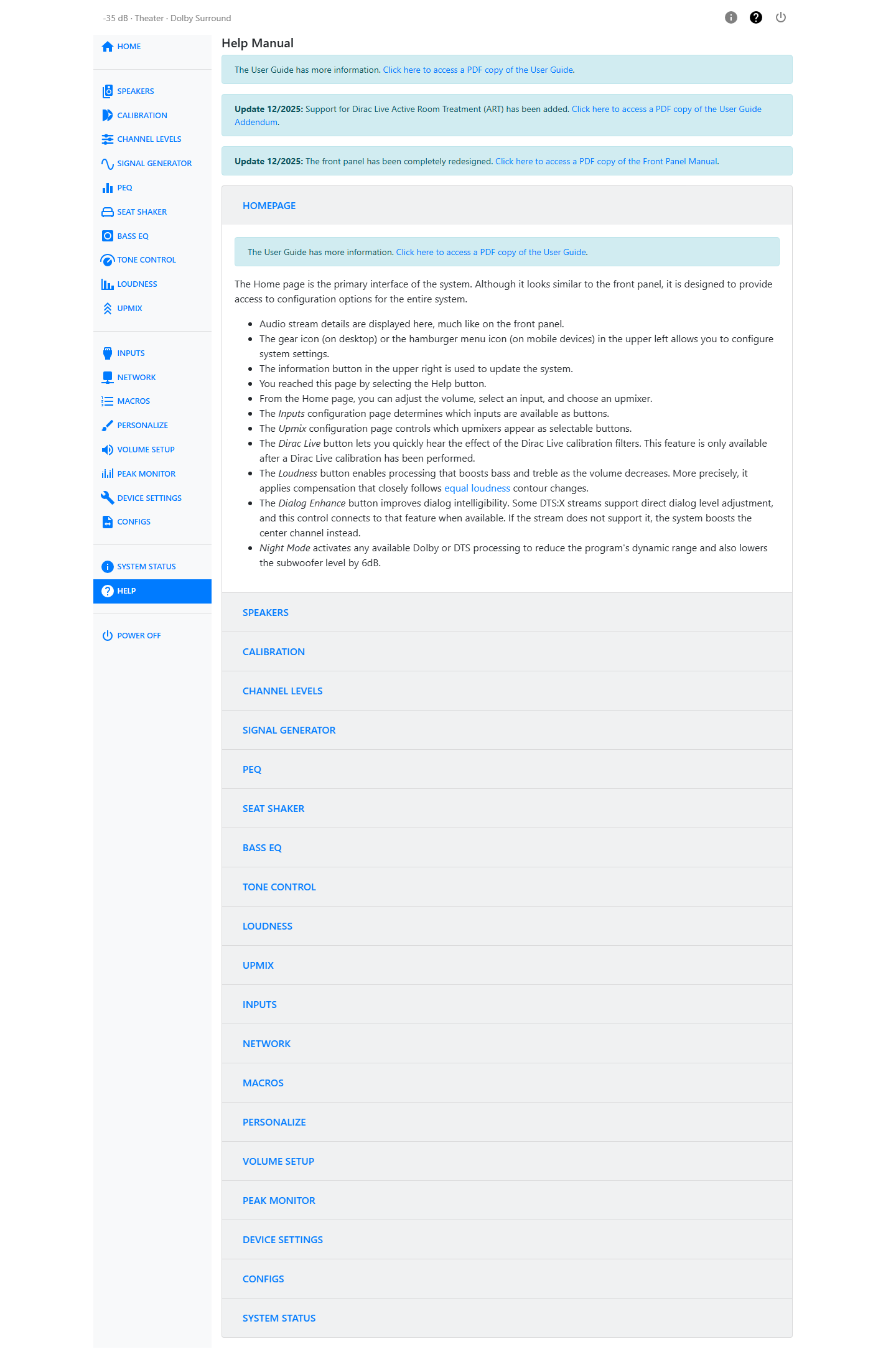
The ? button in the top-right corner of every page opens Help, a set of sections — one per settings page — that explains the controls on the page you came from.
The i button opens System Status, which displays the software version, release notes, and update history. It is also the place from which you can check for and install system software updates.
The power button opens a confirmation dialog that lets you put the unit into standby, restart it, or power it off completely.